A Digital Theremin Built With Off-the-shelf Components
Note: This article describes a project that I built for myself. It is not a product that I am manufacturing or offering for sale. At this time, I am not publishing the schematics, PCB layouts, firmware, or software used in this project. I may publish it at some point in the future.
Introduction
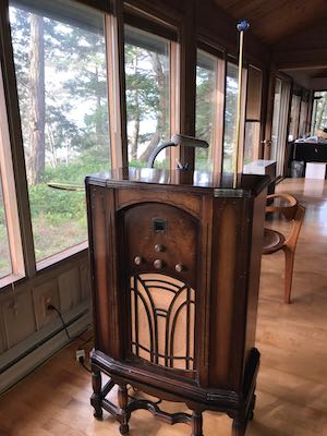
Over the course of a year in 2014-2015, I designed and built a vacuum tube theremin. Although my design was original, it was based on the same principles as the designs of Léon Theremin. I have been very satisfied with the performance of my vacuum tube theremin, and I have gotten many hours of enjoyment from playing it. But as an engineer, I recognize that the traditional theremin designs suffer from some inherent shortcomings:
- The pitch circuit involves three interacting tuned circuits—two oscillators plus the antenna and antenna coil—which must be carefully adjusted to tune the theremin for the best musical range, sensitivity, and linearity of the pitch field. Tuning a traditional theremin—especially the initial tuning—is not an easy task.
- The oscillators in a traditional theremin can drift in frequency due to aging of components and changes in temperature and humidity. Small changes in frequency can result in large changes in the behavior of the instrument. Although careful design and component selection can yield oscillators which are surprisingly stable, this problem is inherent and cannot be eliminated entirely.
- Nothing in the design guarantees a linear pitch field. To the extent that the pitch field can be made linear, it is the result of a happy accident involving the response curves of the oscillators and the antenna circuit, the electric field between the player's hand and the antenna, and any stray coupling between the fixed and variable pitch oscillators.
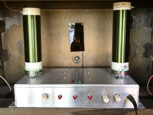
Since building my original theremin, I have spent a lot of time pondering how its limitations could be alleviated through modern digital design techniques. In 2019, I started experimenting in earnest. After trying many approaches that proved to be disappointing, I found one that worked very well. This culminated in a finished instrument in mid-2020. Except for some hand-wound coils, the digital theremin is built from readily available off-the-shelf components.
The Theremin Challenge in a Nutshell
Stripped down to its bare essentials, a theremin can be described as a device that measures very small values of capacitance. The player's hand—and, to a lesser extent, his or her body—is one plate of a capacitor. The antenna is the other plate, and the air in between is the dielectric. Changes in the distance between the two plates, or in the shape formed by the hand, cause changes in the electric field between the player and the antenna. This changes the value of the capacitance seen by the antenna. The capacitance of this configuration is very small—usually less than 1 picofarad for the pitch antenna, and slightly more for the volume antenna. The challenge for a digital theremin is to measure such a small capacitance and convert it to a number that can be processed by a computer.
Analog Devices manufactures a "24-Bit Capacitance-to-Digital Converter" chip, the AD7747. I hoped it would prove to be a simple solution to this problem, and on paper its specifications seemed adequate. But in practice it turned out to be too slow and too susceptible to noise. After trying many different approaches, I settled on the method described in the following section.
How It Works
The solution that finally succeeded is shown in the diagram below. A digital sine wave generator, the Analog Devices AD9833, produces a very stable (crystal controlled) sine wave at a frequency of about 350 kHz. The actual frequency is controlled precisely by the software running on a microcontroller. The sine wave drives a large inductor L1 (about 13-16 mH) which is connected to the pitch or volume antenna. The player's hand forms a capacitance which is effectively between the antenna and ground. This capacitance, the inductance L1, and various parasitic losses constitute a series resonant RLC circuit.
When the RLC circuit is at resonance, the current through the circuit is in phase with the driving sine wave. As the player's hand moves, the capacitance increases or decreases, changing the resonant frequency. This causes the phase of the current to vary between -90° and +90° relative to the driving voltage.
A smaller inductor L2 is nested inside L1, forming a loosely-coupled transformer that is used to sense the current in the RLC circuit. The current through L1 creates a magnetic flux which in turn generates a current through L2. The two currents are in phase with each other at all times. The induced current in the sense coil L2 induces a voltage across L2 which leads the current by 90°. Therefore, when the RLC circuit is at resonance, the sense voltage across L2 will have a phase of +90° relative to the driving voltage. As the hand moves, the phase of the sense voltage will vary between 0° and +180°.
The driving signal and the sense signal are fed into comparators which detect the zero-crossings of the sine waves. A high-speed timer in the microcontroller measures the interval between the rising edges of the two signals. Knowing this interval and the frequency of the driving signal, the software can calculate the phase relationship betwen the two waveforms.
In a series RLC circuit such as this, the current is highest at the resonant frequency, and it drops off rapidly on either side of that point. In order to keep the sense voltage as strong as possible (and therefore as immune from noise as possible), the software constantly adjusts the frequency of the oscillator to keep it at the varying resonant frequency of the RLC circuit. As the player's hand moves closer to the antenna, the capacitance increases and the resonant frequency decreases. The software senses the change in phase and adjusts the oscillator frequency to move it back toward resonance. This type of arrangement is called a software phase-locked loop (PLL).
The net effect of all this is that the software varies the oscillator frequency in response to the motions of the player's hand. The oscillator frequency corresponds to the distance from the hand to the antenna, and it is used to control the pitch or the volume. The circuit and software described here are duplicated for the pitch and volume antennas.
The Implementation
From the description above, it should be clear that the software has to do a lot of things very rapidly. On each channel (pitch and volume), it needs to measure very small time intervals (about 700 nsec) with great precision. For noise immunity, it has to take batches of such measurements and average them together. It must do this about 1000 times per second on each channel in order to keep the oscillator frequencies properly adjusted for resonance. About 100 times per second, it must update the pitch and volume of the audio tone based on the latest oscillator frequencies. In addition, it synthesizes the audio tone in software at a sampling rate of 48 kHz. That is a lot of processing, and when I began the project I wasn't at all sure it would be possible.
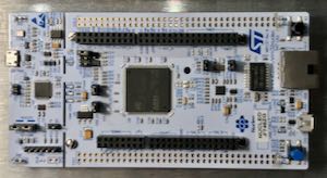
To handle all of this computation, I decided to use the STM32F746ZG microcontroller chip. It is a powerful 32-bit ARM processor running at a clock frequency of 216 MHz. The chip contains 1 MByte of flash memory and 320 kBytes of RAM. It also includes numerous on-chip peripherals, including 14 precision timers, a 12-bit digital-to-analog converter (DAC), three 12-bit analog-to-digital converters (ADC), numerous general-purpose I/O pins (GPIO), and various communication interfaces—all in a package less than 1" square.
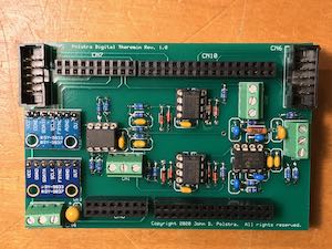
To simplify development, I bought a Nucleo-F746ZG development board. This low-cost board (about $24) contains the microcontroller chip and the I/O connectors needed for interfacing to it. The board also includes a built-in programmer for the flash memory, accessible via a USB port. I designed a daughter board to hold the oscillator modules, comparators, and audio circuitry. The daughter board plugs directly into the connectors of the Nucleo board in a piggyback fashion. I included connectors for wiring up three pushbutton switches, two rotary encoders, and two LEDs. I wasn't sure what I would use them for, but that could be determined later by the software.
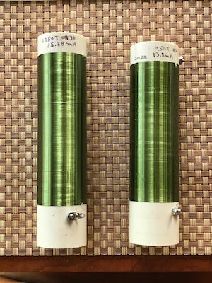
I wound the antenna coils using 36 AWG wire on lengths of 1.5" nominal Schedule 40 PVC pipe. The actual outside diameter of this pipe is 1.9". I wound 1050 turns for the volume antenna coil, yielding an inductance of 15.68 mH. For the pitch antenna coil, I wound 950 turns for an inductance of 13.8 mH. These values are not critical at all, since the software can adjust itself automatically to a wide range of inductances. However, I intentionally gave more inductance to the volume antenna coil to ensure that its resonant frequency would not be close to that of the pitch antenna coil. If the two antenna circuits were operated at nearly the same frequency, they likely would interfere with each other.
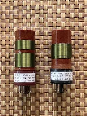
For the two sense coils, I used coils that I had already wound for a different project. Each sense coil is 70 turns of 30 AWG wire, wound on a 1-3⁄16" diameter Garolite tube. The sense coils have an inductance of about 130 µH, and they are mounted on octal vacuum tube bases as an easy way to pass their connections through the chassis top. In the photographs you will see that the sense coils each have two windings, but I used only the larger windings for this project. The sense coils plug into tube sockets on the chassis, and the antenna coils are mounted around them using circular capacitor clamps.
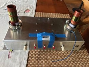
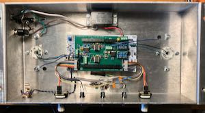
I mounted the electronics inside a small metal chassis along with a power supply, the pushbuttons, encoders, and LEDs, and a potentiometer to serve as a master volume control. (The volume control was added after I took the photo at right.)
Initial Testing
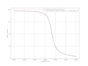
After installing the chassis in the cabinet and connecting the antennas, I needed to run some tests to make sure the circuit was working properly. I wrote a software function to sweep each oscillator over the relevant frequency range and record the phase measurements. I plotted the phase vs. frequency data and used a least-squares method to fit an ideal RLC circuit model to the data. The plot at right shows the results for the volume antenna. The pitch antenna produced similar results. As you can see, the phase measurements are quite free from noise, and they follow the ideal RLC model closely.
The Software
The software running on the microcontroller is written in C and compiled using the GCC compiler. I used the STM32CubeMX application and the ST Microelectronics HAL (hardware abstraction library) to generate drivers for the peripherals such as the timers, DAC, etc. I also used the FreeRTOS real-time operating system to provide support for multiple threads of execution for the various tasks that the software must perform.
For the phase measurements, I programmed one of the timers in "input capture" mode. In this mode, the timer records the precise times when the rising edges of the drive and sense waveforms on each channel occur. This timer runs at 216 MHz, giving it a resolution of 4.63 nsec. When it is triggered to start, this timer records the times of 32 consecutive rising edges on both the drive and sense waveforms of either the pitch or volume channel. It uses direct memory access (DMA) to save the timestamps directly to RAM without any intervention by the software. A separate timer triggers these batch measurements 2000 times per second, alternating between the pitch and volume channels.
When a batch of 32 such measurements completes, a software thread is awoken to process the measurements. It subtracts the timestamps of the drive and sense edges and then averages them to get a time difference which is relatively free from noise and jitter. From this time difference and the frequency of the oscillator (which is known since the software controls it), it determines the phase shift between the drive and sense signals. It then adjusts the oscillator frequency appropriately to keep the phase locked at 90°. This happens 1000 times per second on both the pitch and volume channels.
A separate thread runs 100 times per second to transform the two oscillator frequencies into appropriate values for the audio pitch and volume. I determined experimentally that 100 updates per second is fast enough to ensure that even the most rapid hand movements sound smooth in the generated audio.
Converting the oscillator frequencies into pitch and volume settings is an interesting challenge, particularly for pitch. The holy grail for a theremin is a linear pitch field, which means that an octave is the same size whether played near the antenna or far away from it. So conceptually, the software first converts the oscillator frequency into a hand distance from the antenna, and then the hand distance is converted into a pitch. In practice, these two calculations are merged into a single step for efficiency.
I determined the transformation from oscillator frequency to hand distance experimentally, through a process that will be described below.
Next we come to the actual generation of the audio tone. I could have done this with a third digital oscillator chip, but I decided to try to generate the tone in software for greater flexibility. The waveform to be generated is stored in memory as 16,384 samples making up one cycle of the wave. A software thread runs 1000 times per second, loading batches of 48 samples (selected appropriately to generate the desired pitch) into a RAM buffer to be output to the DAC at a 48 kHz sample rate. As it loads the batches into the buffer, the software multiplies their values by the current volume level. Meanwhile, a hardware timer takes the samples from the buffer using DMA and sends them to the DAC to generate the audio tone. A 4th-order active analog low-pass filter on the circuit board filters the audio to eliminate aliasing caused by the sampling. I should mention here that the digital oscillators driving the antenna circuits do not need any filtering, because the resonant RLC circuits of the antennas already filter out any aliased frequencies.
I mentioned above that the waveform is stored in memory. This is done just once at power-up. The waveform can be anything that is desired. Currently, I have it set up to try to emulate the tone of Clara Rockmore's theremin. I took a sample of it from a recording ("Clara Rockmore's Lost Theremin Album") and did a Fourier analysis to break it down into its harmonic components. These components are used by the software at power-up time to synthesize the waveform. After power-up, the waveform can be modified by turning one of the rotary encoders, which emphasizes or attenuates certain harmonics to act as a sort of tone control.
I have also experimented with applying a digital filter to the generated waveform before it is output to the DAC. That makes the sound more natural by varying its harmonic content as the pitch changes. There appears to be plenty of processing power available for this sort of thing, so there is room for much more experimentation.
Finally, the software includes a diagnostic thread which listens for commands on a serial port that is connected to a USB-to-serial converter on the Nucleo-STM746ZG board. By connecting the USB port to a computer, I can gather diagnostic information and send commands to the software to put it into special modes of operation. I used this feature for determining the transformation from oscillator frequency to hand distance, as described next.
Calibration
To achieve a linear pitch field, we have to be able to determine the hand distance from the oscillator frequency that yields resonance. Mathematically, this is practically an intractible problem; we have to measure it somehow. But how can it be done? A player can hold his hand at various distances from the antenna, but as soon as we hold up a ruler to measure the distance, we interfere with the electric field and ruin the measurement. I had to give this a lot of thought before I came up with a satisfactory solution.
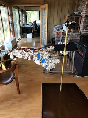
For my first attempt, I constructed an artificial hand mounted on a microphone stand. I took a glove, stuffed it with various fillers, wrapped it in aluminum foil, and grounded the whole mess. With this setup, I could set the hand at a precise distance from the antenna, and then step away from the instrument to record the oscillator frequency using the diagnostic interface mentioned above. I did this for 1" increments to the edge of the usable pitch field. The results were somewhat useful, but they weren't very realistic. In practice, a player's body is present in close proximity to the antenna, exerting a significant influence on it.
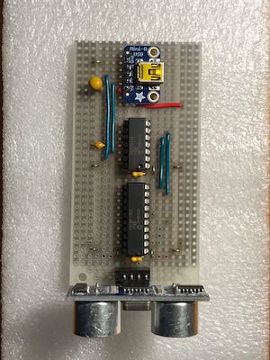
Finally, I realized that I could measure the distance using an ultrasonic ranging device, without creating any interference with the operation of the theremin. I built the unit shown at left, with a ranging unit, a PIC microcontroller, and a USB-to-serial converter. I programmed the PIC chip to report the distance whenever it is commanded to do so via the USB interface. I set up the theremin such that the ranging unit was aimed at a window, with the pitch antenna a known distance from the window. I strapped the ranging unit to my wrist at a fixed distance from my fingertips. The ranging unit measured the distance to the window, from which I could determine the distance between my hand and the antenna.
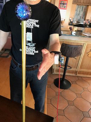
I connected both the ranging unit and the theremin's diagnostic interface to a Raspberry Pi computer with USB cables. A simple Python program running on the Raspberry Pi queried both the ranging unit and the theremin at a rapid rate. In response, the two devices reported the distance and the oscillator frequency, respectively. As I moved my hand through the extent of the pitch field, the Python program recorded these values to a file for subsequent analysis. In this way I was able to plot a curve relating the oscillator frequency to the hand distance.
Up to this point in the discussion, I have referred to the oscillator frequencies for the pitch and volume antennas. In reality, the frequencies are not used directly. The software uses a more roundabout calculation which allows it to calibrate itself automatically for different playing environments. After the player powers up the instrument, he stands in the resting position with the hands withdrawn. The software measures the oscillator frequency, which corresponds to the resonant frequency of the antenna circuit at rest. Since the value of each inductor is known, the software can easily calculate the intrinsic capacitance of the antenna from the resonant frequency. All other calculations are based on the "extra" capacitance ΔC added by the player's hand.
Controls
The rotary encoders and pushbuttons are currently used as follows. The most important control is the left-hand encoder, which adjusts the pitch field. Internally, the pitch field is calibrated in terms of inches per octave; i.e., how many inches the hand must move to change the pitch by one octave. I set the default to a value that works best for myself, but it can be adjusted using the left-hand encoder. Each click of the knob increases or decreases the pitch field by ¼ inch per octave.
As mentioned previously, the right-hand encoder is a tone control. It emphasizes or attenuates the harmonics of the waveform to make it sound brighter or darker.
The left-hand pushbutton controls the pitch range (the register) of the audio tone. At power-up the theremin is in the high pitch range. Pushing the left-hand button makes the pitch one octave lower; pushing it again makes it still another octave lower. The next push cycles it back to the high register.
The right-hand pushbutton causes the theremin to recalibrate itself, just as it does when it is initially powered up.
The center pushbutton currently does nothing. I'll dream up a function for it eventually.
Sound Clip
Here is a recording I made with the digital theremin of J. S. Bach's Orchestral Suite #3, 2nd movement, also known as the Air on the G String. For this recording, I ran the theremin direct into a Boss BR-864 recorder, without any special effects or equalization.
I am better at building theremins than playing them. Please try to overlook the flaws in the performance!
Copyright © 2020 John D. Polstra. All rights reserved.