A Transformerless Constant-current Reverb Driver
Introduction
Vacuum tube reverb circuits traditionally have used a low-impedance reverb tank coupled to the driver tube by a small output transformer. But that is not the only way to drive a reverb tank using a vacuum tube, and in fact it is not the best way. In this article, we present a reverb circuit that eliminates the transformer and drives the reverb tank better than traditional circuits. Our circuit drives the tank better because it is a constant-current driver instead of a constant-voltage driver.
Constant-voltage vs. Constant-current Drive
Let's first understand the difference between constant-voltage drive and constant-current drive. These terms refer to how the signal applied to the reverb tank varies over the frequency range of the amp. A constant-voltage driver—the traditional kind—delivers approximately the same voltage to the tank regardless of frequency. A constant-current driver, on the other hand, pushes a constant signal current through the tank for all frequencies. If the impedance of a reverb tank were purely resistive, there would be no distinction between the two. By Ohm's law, the current through a resistor is directly proportional to the voltage across it. If the voltage is constant, then the current is constant as well.
But a reverb tank is not a resistive load; in fact, it behaves almost exactly like an inductor. The impedance of an inductor is proportional to the frequency of the signal applied to it. If you double the frequency, the impedance doubles as well. Because of the inductive nature of a reverb tank, a constant-voltage driver does not produce a constant current through the tank. For example, the current produced by a 2 KHz signal would be about half that produced by a 1 KHz signal.
We apply a signal to a reverb tank in order to produce mechanical motion in its springs. It turns out that the amount of motion is proportional not to the voltage, but rather to the current that is passed through the tank. More precisely, the mechanical motion is proportional to the product of the current times the number of turns in the driver coil of the reverb tank. For a given tank, the number of turns is of course constant. So, to drive the tank equally at all frequencies, we want a constant-current driver. That is in fact what Accutronics recommends.
Implementing Constant-current Drive

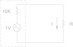
A current source can be simulated by a voltage source with an output impedance that is high relative to its load. Consider the circuit at right. The dashed box contains a 1V source with an impedance of 10KΩ. Suppose the load R is 100Ω. The current I will be 1 / 10100 ≈ 99 uA. Now, if we increase R to 200Ω the current becomes 1 / 10200 ≈ 98 uA. We have doubled the load impedance, but the current through it has decreased only about 1%. Because the impedance of the source is much higher than that of the load, it functions as a constant-current source.
Vacuum tubes are high-impedance devices. In particular, a typical amplifier pentode has a very high plate resistance of 200KΩ or more. If you look at the plate curves of a pentode, you'll see that the plate current stays almost constant over a wide range of plate voltages. Pentodes are inherently constant-current devices. If we choose a reverb tank with an appropriate input impedance, we should be able to drive it directly from a simple pentode stage.
A Practical Design
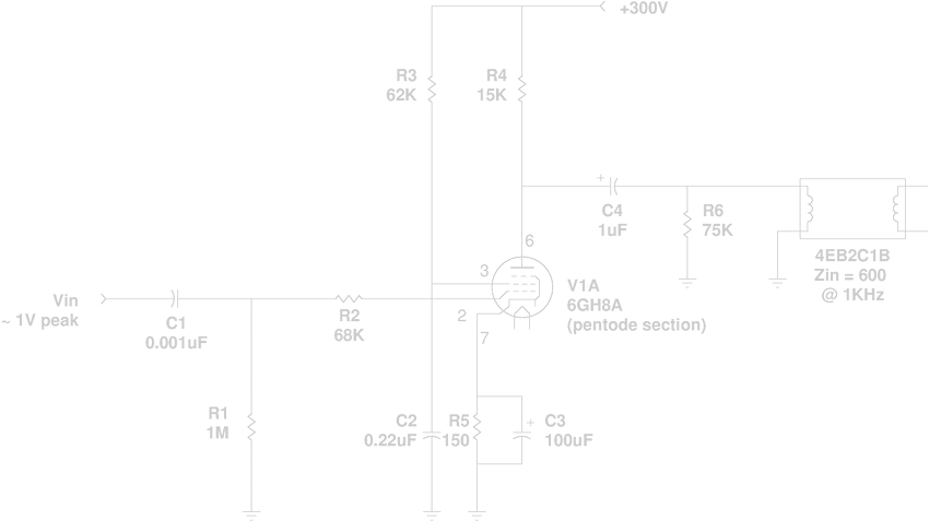
The circuit below works very well in practice. We chose the 4EB2C1B reverb tank, with a nominal input impedance of 600Ω @ 1 KHz. According to the Accutronics data, this tank can be fully driven with a signal of 3.2 mA RMS ≈ 4.5 mA peak. Since many RF amplifier pentodes are designed to run at a plate current of 10–15 mA, this should be easily achievable. We chose the pentode half of a 6GH8A triode-pentode tube. We used the triode half for the reverb recovery amplifier (not shown). Many other RF pentodes would work equally well, if biased properly. For example, a 6AU6A or the pentode section of a 6U8A should work fine, as should a small power pentode such as a 6AK6 or 6G6.

The tube must be biased to a plate current sufficient to supply the necessary signal (4.5 mA peak) to the reverb tank. But we don't want the plate current to be too high, or the plate resistor R4 will need to be too small, lowering the output impedance of the driver. The tube in this circuit idles at about 7.6 mA. A plate resistor of 15KΩ gives us a plate voltage of 186V, allowing for plenty of signal swing both positive and negative.
The output impedance of the driver is essentially equal to R4, since the plate resistance is so high that it can be ignored. Now we must make sure that a 15K output impedance is high enough to qualify as "almost constant-current". It must be large relative to the impedance of the tank at the highest frequency of interest. Guitar speakers generally roll off everything above about 5 KHz, so we will use that as the maximum frequency. The nominal impedance of the tank is 600Ω @ 1 KHz. At 5 KHz, the impedance will be five times the nominal, or 3000Ω. The output impedance of 15KΩ is five times that—more than sufficient.
R6 keeps the proper DC voltage on the output capacitor C4 in case no reverb tank is connected. Any value much larger than the tank impedance will do for this resistor.
The value of C4 might at first seem too small for good low-frequency response. In a normal amplifier circuit, it would be chosen large enough to keep the frequency response flat down to the lowest frequency of interest. With a minimum frequency of 100 Hz, for example, the impedance of the tank is 60Ω. That would imply a value for C4 of at least 25 uF. But in fact, C4 does not need to be nearly that large. The reason is that this is a constant-current driver. It supplies the proper current to the tank as long as the combined impedance of the tank and C4 are much less than the output impedance of 15KΩ. Thus C4 can be calculated based on the output impedance of the driver, rather than on the input impedance of the reverb tank.
The input capacitor C1 was given a rather small value in order to roll off the response below about 160 Hz. This helps to keep low frequency rumble out of the reverb tank. It is to some extent a matter of taste; you may wish to use a larger or smaller value here.
Performance
Here are the results of a simulation using LTspice. For the simulation, the value of C1 was set to 0.01uF in order to remove the artificial low-frequency roll-off discussed above. As you can see, the signal current through the reverb tank is virtually constant over the entire frequency range.

But how does it sound? To find out, we added the circuit to a prototype amp we've been working on.† Here's a sound clip:
Conclusion
In a vacuum tube amp, there is really no need for a reverb transformer. With the right circuit design, you can get better performance driving the reverb tank directly.
†The amp is a single-ended amp that puts out about 10W using an EL34 or KT77 power tube. The sound clip was recorded simply by placing a Zoom H2 digital recorder a few feet away from the speaker cabinet. The clip was taken directly from the recorder without any additional processing.