A Vacuum Tube Theremin
WARNING
This is not a project for beginners. It uses high voltages which are lethal. Proper safety procedures must be rigorously followed at all times when working on this circuit or any other vacuum tube circuit.
To build a theremin such as this, one needs to have quite a bit of experience with both audio frequency and radio frequency construction practices. Physical layout of the circuit is critical, as every length of wire acts as an inductor, capacitor, and antenna. The cabinet and antennas are part of the circuit; their physical details affect its operation.
Tuning up a new theremin is an involved process which is not described here. To do it easily requires a sine wave generator capable of frequencies approaching 1 MHz., an oscilloscope, and a frequency counter.
Introduction
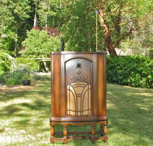
In the Spring of 2014, I began to develop an interest in the theremin. It all started when my bandmate Anita, an accomplished multi-instrumentalist, gave me a lesson on the musical saw. Being an electronics guy, I was reminded of the theremin by the eerie yet beautiful sounds of the saw.
Around the same time, a friend gave me a beautiful 1933 Crosley radio that had been in her family for more than 80 years. Although the radio was dead when I received it, I was able to restore it to working condition without too much trouble. I found a good spot for it in my home, but soon noticed that I practically never used it. It was, after all, just an AM radio—and, by modern standards, not a particularly good one.
The one thing the radio had going for it was its cabinet. It stood waist high, with beautiful carved woodwork and a lovely grille for the speaker. The cabinet was made of real solid wood, not veneer. Its knobs were wooden, as well. And the cabinet was in excellent condition, despite its age. I decided it would make a very cool-looking theremin.
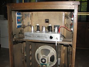
Over the course of the next year, I studied every theremin design I could get my hands on. Though I already had a basic understanding of the principles behind the theremin, I knew next to nothing about the engineering challenges in designing a practical instrument that was both stable in operation and sensitive enough to be as playable as possible.
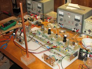
I studied all of the various RF oscillator topologies and learned the pros and cons of each. I breadboarded a bunch of them to see which ones worked the best. I wrote software to help me design the coils I would need; built a coil winder to wind them; and constructed an LC meter from a kit so I could check the results. I made antennas from copper tubing and measured their capacitance over a range of hand-to-antenna distances. I wrote software to simulate the essential parts of the oscillator and antenna circuits, so I could find out how linear each design would be in terms of the pitches of the musical notes. I investigated mixer circuits for combining two RF signals to produce a musical note. I looked into different ways to modulate the volume. Finally, I breadboarded several complete designs to make sure the end result would play as intended. In short, I immersed myself in the theremin and had a whole lot of fun.
Circuit Description
From the beginning, I knew I wanted to use vacuum tubes rather than solid state components. I have a business building and repairing tube guitar amps, and I grew up messing around with tubes in the 1960s, when they were still very much a mainstream technology. I'm comfortable working with them and I have the right equipment and tools for building things with them. I liked the challenge of designing a "vintage" circuit that would perform well, and besides, it just seemed wrong to put a modern solid state circuit into a cabinet built in 1933.
Pitch Oscillators
Figure 1 shows the variable pitch oscillator (VPO), the fixed pitch oscillator (FPO), and the mixer circuit. V1, a 12AU7A dual triode, forms the VPO. It is a cathode-coupled oscillator. The left-hand triode acts as a cathode follower. Its voltage gain is slightly less than one, but it has a low output impedance. The output is coupled into the cathode of the right-hand triode, a grounded-grid voltage amplifier. Both stages are non-inverting, so the output from pin 6 is an amplified version of the input on pin 2, and the two signals are in phase with each other. Capacitor C1 couples the output back into the input and provides the positive feedback necessary for oscillation.
The plate load on pin 6 is a parallel LC resonant circuit consisting of inductor L1, capacitors C2 and C3, and the pitch antenna circuit. At resonance, the circuit presents a high impedance with zero phase shift, setting the frequency of oscillation. C4 blocks the DC plate voltage from the antenna to prevent shock; with respect to the RF signal, it is essentially a short circuit.
Resistor R2, although not strictly necessary, was found experimentally to improve the stability and reliability of the oscillator. R4 and C5 decouple the circuit from the power supply.

V3 implements the FPO. The circuit is identical to the VPO, except for one detail. The FPO has no antenna circuit. In its place is a variable capacitor C15 for tuning the instrument. You will notice that while L3, C12, and C13 connect between the plate and the positive supply, C15 connects instead from the plate to ground. But since the power supply acts as a short circuit for AC signals, the positive supply is effectively at RF ground potential; hence C15 is effectively in parallel with C12 and C13. It is wired in this way because its metal shaft is connected to its rotor plates. The shaft must be at ground potential, both to prevent an electrical shock hazard and to eliminate interference from the hand touching the shaft. Coupling capacitor C14 is not strictly necessary, but it provides an additional measure of safety by isolating DC voltages from the tuning capacitor. C14 is so much larger than C15 that it is effectively a short circuit for RF signals.
The VPO and the FPO oscillate at around 270–275 kHz. The frequencies of the oscillators are tuned such that the VPO oscillates at a slightly lower frequency than the FPO.
Pitch Antenna Circuit

The pitch antenna circuit is a series RLC resonant circuit made up of inductor L2, its intrinsic resistance, and the parallel combination of the antenna's intrinsic capacitance and the capacitance of the player's hand in proximity to the antenna. This is illustrated in the schematic at right.
The pitch antenna circuit is connected in parallel with the tank circuit of the VPO. The VPO is tuned to a frequency slightly higher than the resonant frequency of the antenna circuit. At such a frequency, the antenna circuit presents an inductive impedance; i.e., it behaves as an inductor in parallel with L1. Close to the resonant frequency of the antenna circuit, the effective inductance is small; farther from it, the inductance is larger.
Inductors in parallel combine in the same way as resistors in parallel. The combined inductance is less than either of the individual inductances. Thus, the antenna circuit raises the frequency of the VPO. When the hand is distant from the antenna, Chand is zero and the resonant frequency of the antenna circuit is at its highest; i.e., it is closest to the frequency of the VPO. Under this condition, the effective inductance in the tank circuit is at its minimum and the VPO frequency is at its maximum.
As the player's hand approaches the antenna, Chand increases and the resonant frequency of the antenna circuit decreases. This moves the resonant frequency of the antenna circuit farther below the oscillating frequency of the VPO. Farther from resonance, the effective inductance of the antenna circuit, and thus of the VPO's tank circuit, become greater—causing the VPO frequency to decrease.
Since the audio tone is produced by the difference in the FPO and VPO frequencies, lowering the VPO frequency increases the pitch of the musical note. Therefore, the pitch rises as the player's hand moves nearer to the antenna. Most importantly, this arrangement greatly magnifies the effect of small changes in Chand, making the instrument sensitive to small hand movements. Herein lies the real genius of Léon Theremin's invention.
In summary, here is the relationship among the frequencies of the two oscillators and the resonant frequency of the antenna circuit: fantenna < fvpo < ffpo.
Mixer
The RF signals from the VPO and the FPO are mixed in V2, a 6L7 pentagrid mixer tube. The 6L7 was introduced in 1936 for use in radio circuits. Unlike the pentagrid converters used in many AM radios, the 6L7 is strictly a mixer; it does not function as a local oscillator in radio circuits. The 6L7 can be thought of as a pentode with a couple of extra grids. Grids 2 and 4 are screen grids, internally connected to each other and normally supplied with a fixed voltage of about 100V just as they would be in a pentode. Grid 5 is the suppressor grid, internally connected to the cathode.
The signals from the VPO and FPO are coupled by C6 and C7 into grids 1 and 3, respectively. Each of these grids controls the current flow to the plate. In effect, the 6L7 multiplies the two grid signals are together to yield the signal on the plate. The result is a combination of four different frequencies: the original VPO and FPO frequencies, their sum, and their difference. If the VPO and FPO oscillate at nearby frequencies, as they do by design in a theremin, the difference frequency is an audio tone. The other three frequencies are all in the RF range and can be filtered out easily.
Volume Oscillator
The volume oscillator, shown in figure 2, is a simple Colpitts oscillator utilizing half of a 12AU7A dual triode tube. (The other half is unused.) Inductor L201 together with the series combination of capacitors C201 and C202 set the operating frequency. The output is taken from the cathode of the tube. RF choke L202 completes the DC circuit to the cathode, while presenting a relatively high impedance to the AC signal.

Inductors L203 and L204, along with the intrinsic capacitance of the antenna and the capacitance of the hand near the antenna, form a series resonant RLC circuit from the oscillator output to ground. As the hand moves closer to the antenna, the capacitance increases, lowering the resonant frequency of this RLC circuit.
The volume oscillator is tuned to oscillate just slightly higher than the resonant frequency of the antenna circuit when the hand is far from the antenna. At resonance the impedance of a series RLC circuit is at its minimum, and thus the current through it is at its maximum. Consequently, the AC voltage across L203 is at its maximum. Thus, when the hand is distant, a large AC signal appears at VOL_OSC_OUT.
As the hand moves nearer to the volume antenna, the resonant frequency of the antenna circuit decreases and the circuit moves away from resonance. The current through the antenna circuit decreases, and so does the AC signal at VOL_OSC_OUT.
Hence, VOL_OSC_OUT has an AC signal whose amplitude is large when the volume should be loud, and small when the volume should be soft.
The volume oscillator oscillates at a frequency of about 351 kHz.
Volume Modulator
To control the volume, we again used the 6L7 tube. By changing the bias on grids 1 and 3, we can vary the transconductance of the tube over a wide range. In an amplifier stage, this can vary the voltage gain from near 0 (at cutoff) to a maximum value that depends on the plate load. Figure 3 shows the circuit.
MIX_OUT, the output from the RF mixer, is first passed through an RC low-pass filter to remove all but the audio signal. The filter consists of R9, the plate resistor of the mixer stage, and C101. C102 couples the filtered audio signal, a slightly distorted sine wave with relatively little harmonic content, into a wave shaping circuit designed to produce the somewhat buzzy classic theremin tone.
D104 and R109 form a simple half-wave rectifier which passes only the positive half of the sine wave. D103 and R101 apply an equal load on the negative peaks. Without D103 and R101, C102 would charge up to a DC potential that would bias D104 nearly into cutoff over the entire cycle. Note that the two diodes are Schottky rectifiers, which I chose because of their low forward voltage drop. Standard silicon diodes (1N914, 1N4148, etc.) work almost as well here, giving a slightly lower output signal. In either case, the signal at the junction of D104 and C103 is a half-wave rectified sine wave, positive peaks only.

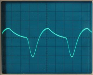
C103 couples this signal into the control grid of V4, which amplifies (and inverts) the signal. The value of C103 is intentionally small, such that C103 and R102 form a high-pass filter. This causes the flattened portion of the waveform to sag (decay exponentially), further increasing the harmonic content of the tone. From the plate of V4, the signal is coupled into the volume control and sent to the output jack. C111 helps filter out any remaining RF components from the output. The photo at right shows the final waveform, which is similar to the waveform generated by clones of the famous Clara Rockmore theremin.
Grids 1 and 3 are both biased at ground potential, and the gain of the stage is controlled by changing the cathode voltage. As noted in the previous section, VOL_OSC_OUT is an RF signal which has a high amplitude when the hand is distant from the volume antenna, and a low amplitude when the hand is near the antenna. This signal is rectified to a negative voltage by a voltage doubler consisting of C110, D102, D101, and C108. The DC output of the voltage doubler is referenced to about +42V by the voltage divider R107 and R108. The net effect is that the output of the voltage doubler varies from 0V or less when the hand is distant from the antenna (maximum volume) to +30V or more when the hand is near the antenna (minimum volume).
Transistor Q1, a PNP emitter follower, couples this control voltage to the cathode of the 6L7 via the current limiting resistor R105. At maximum volume, this sets the cathode at about +3V and thus sets the grid bias relative to the cathode at -3V, yielding a high transconductance and a maximum voltage gain. At minimum volume, the cathode goes to at least +30V, biasing the tube into cutoff where it passes no signal at all. Between these two extremes the volume varies smoothly from loud to inaudible.
Power Supply
Figure 4 shows the power supply. The high voltage secondary of the power transformer is rectified by D301 and D302, and filtered by C301, R301, and C302. From there, the high voltage supply branches off into four separate outputs for different parts of the circuit.
V6 is a gas discharge voltage regulator tube that produces a stable voltage at VBB4 of about 108V. This powers the most critical parts of the theremin, namely, the two pitch oscillators and the screen grids of the two 6L7 tubes.

Ideally, we would power the volume oscillator from this regulated supply as well, but it draws a bit more current than the regulator tube could comfortably handle. Fortunately, the tuning of the volume circuit is quite forgiving, and it works fine even in the face of supply voltage variations. Thus we are able to power the volume oscillator from the unregulated supply VBB1.
The plate voltage of the mixer tube V2 is also very non-critical. We power it from the unregulated output VBB2.
The plate current of the volume modulator V4 varies widely as the volume is changed, from a minimum near zero to a maximum of around 5 mA. To keep the plate voltage fairly steady, we power it from VBB3 which is regulated to 150V by the zener diodes D303 and D304.
Here are some voltages from key points in the power supply. Except for the regulated voltages VBB3 and VBB4, these values are just rough approximations.
- C302: approximately 250V
- VBB1: approximately 150V
- VBB2: approximately 150V
- VBB3: 150V
- VBB4: 108V
Construction
Layout
I constructed the theremin on an aluminum chassis measuring 12½" x 8" x 2½". In laying out the chassis, my goals were to:
- Put the VPO and the volume oscillator close to their respective antennas.
- Separate the three oscillators from each other, so as to minimize interference between them.
- Make the signal paths between sections as short and direct as possible.
- Place the controls and adjustments in convenient locations along the back panel.
- Place the power transformer as far as possible from the rest of the circuitry.
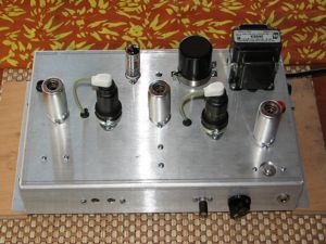
The photo at right shows the chassis as viewed from the player's side (rear) of the instrument. The tubes V1 through V5 run from left to right in the foreground, while V6 is in the center of the background. Along the rear panel, the output jack is at the far right. The large knob next to it is the volume control, and to its left is the tuning capacitor C15. Farther to the left are the trimcaps for the VPO and FPO (C3 and C13). Partially hidden behind V1 and V5, one can see the banana jacks for connecting the antenna circuits.
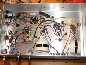
I used point-to-point wiring throughout, mounting the resistors, capacitors, and smaller inductors directly on the tube socket pins and/or to terminal strips. I tried to make each individual stage as compact as possible, while separating the stages enough to prevent them from interfering with one another.
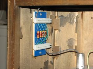
The antenna coils L2 and L204 are made up of series strings of RF chokes. (See below for part numbers.) These coils are mounted external to the chassis, on the walls of the wood cabinet next to their respective antennas. The amount of inductance needed for each antenna depends on the size and shape of the antenna as well as the lengths of the wires leading to and from the inductors. Getting it right requires some experimentation. For that reason, I wired the RF chokes with Eurostyle terminal strips that are in turn mounted on small FR4 boards. With this arrangement, it is easy to add or remove inductance without soldering.
Special Components
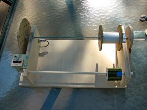
L1 and L3, the inductors for the VPO and FPO, are identical. They are wound on 1.5" (nominal) schedule 40 PVC pipe. The true diameter of this pipe is 1.9". Each coil consists of 30 turns of 30 AWG enamel coated wire, close wound. I used the green wire from Tech Fixx, available on eBay. I wound the coils using a homemade coil winder, and coated them with spray varnish to keep the windings in place.
L201, the volume oscillator coil, is type P-C70-OSC from Antique Electronic Supply. To tune this coil, you will need a plastic hex tool such as the one found in the S-T8454 alignment kit from the same supplier.
L2, L203, and L204 are all made up of Hammond 3-section pi-wound RF chokes which I obtained from Antique Electronic Supply. The Hammond part numbers of the chokes I used are 1535B (2.5mH), 1535D (5mH), and 1535G (10mH). As mentioned above, some experimentation is required with the antenna coils; so, buy some extra RF chokes. In my case, the pitch antenna coil L2 was made up of four 10mH chokes and one 5mH choke, all connected in series. My volume antenna coil L204 was made up of three 5mH chokes in series.
C15, the tuning capacitor, is type 7254173 from Fair Radio Sales. Similar capacitors can be found on eBay.
I purchased the trimmer capacitors C3 and C13 from Antique Electronic Supply. Unfortunately, they no longer sell this part. Similar capacitors appear regularly on eBay.
All of the fixed capacitors I used in the three oscillators were 5% tolerance, zero temperature coefficient (C0G) multilayer ceramic capacitors. I purchased them from Mouser Electronics. I recommend using axial lead capacitors whenever possible; the radial lead devices are tiny and have very short leads.
With 5% capacitors, the pitch oscillator capacitors C2 and C12 can vary by plus or minus 235pF from their nominal value. The 250pF trimmer capacitors I used for C3 and C13 don't have enough range to correct for this. And in any case, the pitch antenna circuit raises the frequency of the VPO a significant amount. Buy a handful of 100pF C0G capacitors to add in parallel with C2 or C12, should the need arise. In my case, I had to add two 100pF capacitors to the VPO.
Antennas
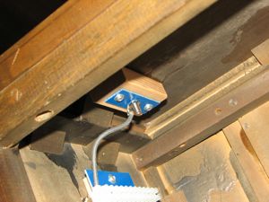
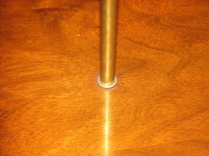
I constructed the antennas from 3/8" outside diameter brass tubing that I purchased in 3' lengths on amazon.com. The pitch antenna is a straight piece 18" long. The volume antenna is the same size and shape as the volume antenna of the original RCA theremin. To form it, I first cut out a plywood template using the drawing and measurements found in this Theremin World article. Then I carefully bent the tubing around the template. I used tubing with a wall thickness of 0.03", after first discovering that thicker-walled tubing was nearly impossible to bend.
The antennas slide into bronze bushings that are press-fitted into holes through the cabinet top and side. I glued wood blocks inside the cabinet to thicken the walls in those places. I soldered banana plugs into the ends of the antennas. They plug into banana jacks mounted just beyond the the ends of the bushings. This arrangement allows the antennas to be removed easily, yet it still makes a reliable electrical connection when they are installed.
Performance
The performance of the theremin has exceeded my expectations. First of all, it is remarkably stable. After an initial warm-up period of a minute or less, its tuning is rock solid, requiring practically no further adjustment over hours of use.
The pitch control works quite well, making for a very playable instrument. Depending on how it's adjusted, it covers more than three octaves of range with ease, and the pitch field is reasonably linear over most of the range. With the theremin tuned as I currently have it, the usable range extends roughly from G2 (97.999 Hz.) to E6 (1318.5 Hz.).
The volume control circuit also works well. It smoothly covers the whole range from silent to full volume. Its response is a bit sluggish for fast staccato notes; however, I believe I can improve that by tweaking a few capacitor values in the volume modulator circuit.
Here is a recording I made with the theremin. The piece is "Après un Rêve", by Gabriel Fauré.
Updates
The theremin described in this article is still evolving, and I make changes to the article from time to time as well. What you see here today may not be the same as what was here yesterday. I'll try to list the major updates here.
- 16 November 2019: Minor clarifications.
- 23 October 2019: Added some detail about the musical range of the instrument; corrected some typos.
- 10 December 2015: Documented some power supply voltages.
- 26 September 2015: Added a recording of the latest version of the theremin.
- 23 September 2015: Added wave-shaping circuitry leading into the volume modulator to get a buzzier, more classic theremin tone. Note, the sound clips haven't been updated yet.